Beam Design Challenge
Summary
As part of a small team, I designed a structural beam out of foam board, capable of sustaining loads of up to 123 lbf (≈547 N).
Category
Coursework: Aerospace & Mechanical Engineering Lab II (AME 20217)
Team Size
2 (myself and one peer)
Skills
CAD (SolidWorks); Engineering drawings; Physical Prototyping
Detailed Breakdown
The main project in this course was to build a beam capable of supporting the maximum possible load in a three-point flexural bending test. My partner and I agreed to base our design on a standard I-beam due to its ‘tried and tested’ reliability and its status as the industry standard for structural beams.
We were provided with only a single 10x40x0.19” sheet of foam board and four glue sticks for construction. This constraint on materials made the task challenging.
Once we agreed on an I-beam-based design, the challenge quickly evolved into optimizing the given material for strength. We sought to minimize the flexural bending stress, 𝜎, by maximizing the area moment of inertia (denoted I ). To give this approach some numerical basis and structure, we computed I for various flange width and stem height combinations. We constrained each attempt by the dimensions of the foam board in order to ensure continuous use of the entire width of the foam board. Once we determined the dimensions which yielded the highest I, we cut the board into three pieces: a vertical stem and two flanges. This used up 330 square inches of material. With the excess 70 square inches of material, we designed additional narrow vertical support columns. To inform our placement of these supports, we generated shear-force and bending-moment diagrams for the 3-point loading configuration.
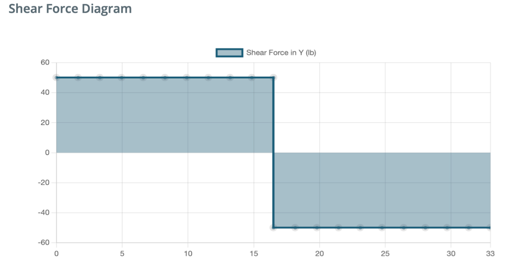
Shear force diagram for a beam undergoing 3-point bending. The x-axis represents the length spanned by the beam (0-33 inches), and the y-axis is the magnitude of the shear force experienced by the beam assuming a load of 100 lbf being applied in the center.
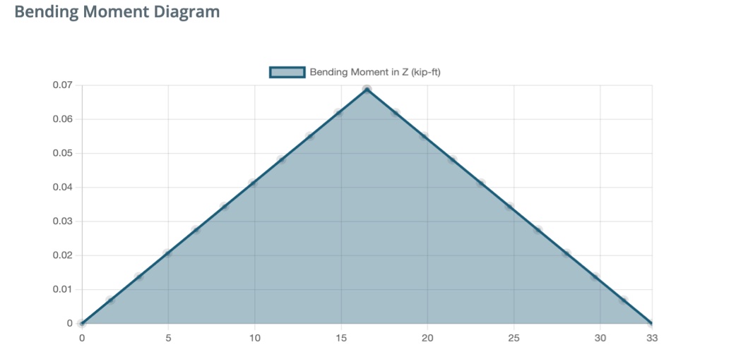
Bending moment diagram for a beam undergoing 3-point bending. Again, we assume a 100 lbf load.
The plots clearly indicate that the maximum support is needed towards the center of the beam, near where the load is applied. We cut the remaining material into fourteen 0.5x6x0.19 inch supports to match the height of the I-beam. On each side of the beam, we placed five supports concentrated in the middle, as well as one halfway to each end of the beam for additional torsional support. A drawing of the CAD model for the initial design is shown below.

Initial design of the beam. The unused material was used to create two horizontal layers of padding to cushion and distribute the pressure applied by the downward loading. This padding is seen in the middle of the topmost face.
My partner and I then produced a physical prototype of the design, using exacto knives to cut sections out of the foam board and hot glue to secure components together (the only permitted materials in the challenge). We thought we could strengthen the construction by cutting grooves and slots into surfaces to allow components to 'puzzle fit' into one another, rather than relying solely on the glue to adhere two flat surfaces together. With our method, the structure would – in theory – become stronger as force was applied to it, with applied force effectively embedding the components deeper inside one another rather than shearing them against each other. In reality, however, even slight imperfections in the grooves (e.g. contact points being a few degrees off from perfect perpendicularity) severely weaken those points of the structure and make it prone to lateral torsional buckling (LTB).
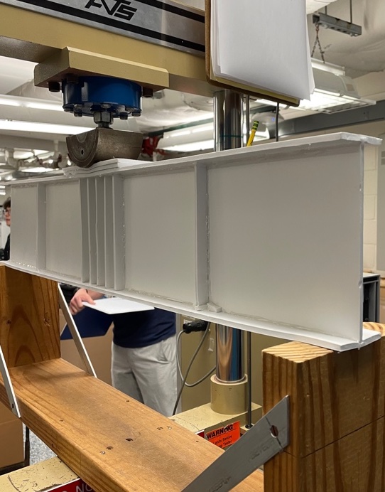
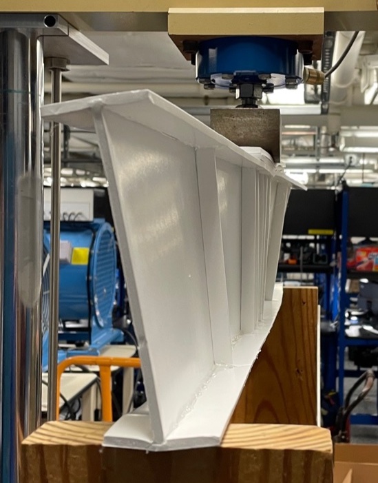
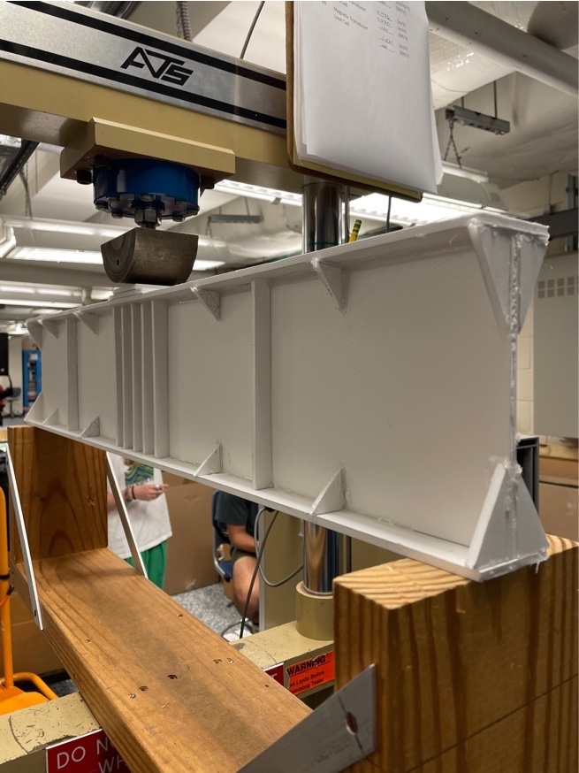
The constructed beam was placed in a three-point bending test setup as shown on the left. It successfully supported a load of 97.6 lbf before failing due to LTB as seen on the right.
We had not anticipated this failure mode; all design focus had been on bolstering structural support around the middle region. The grooves cut in the flange and stem panels contributed to the beam failing in LTB, as they unintentionally caused the beam to twist unpredictably. To address this issue, the major design changes we made for the second iteration were (1) to not carve grooves into the plates and (2) to add gussets of varying sizes along the length of the beam to act as additional supports to discourage failure through LTB. We accomplished this by reallocating some of the material used on flat-lying plates on the top of the beam.

A drawing of the revised beam design. The main strut supports are still present but gussets have been added to provide support against LTB.
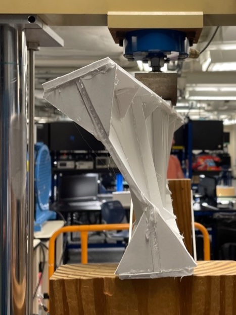
The revised prototype of the beam, shown before and after being subjected to significant loading. LTB is clearly visible as the beam twists about its lateral axis. This version of the beam was able to support a load of 123.0 lbf (a 26% increase in load bearing ability from the original prototype) before experiencing failure.
The beam still failed in LTB, though it should be noted that the gussets certainly functioned as expected. They kept the connections between the stem & flange plates almost perfectly perpendicular, fixing the main failure mechanism from the first test. As such, when the beam failed in the second trial, it was due to the material in the vertical stem plate wrinkling, rather than the plate connections getting twisted.
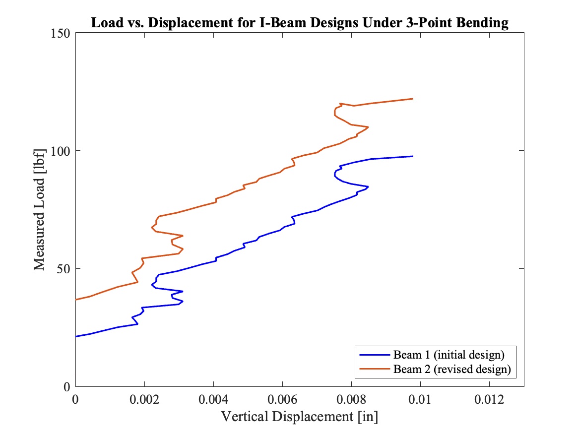
Overall performance of both beams. Uses displacement data from a magnetic transducer and load data from a load cell.