Frisbee Launcher
Summary
As part of a small team, I designed and built a table-mounted rotating arm frisbee launcher.
Skills
CAD (SolidWorks); Engineering drawings; Physical Prototyping; Workshop skills
Team Size
5 (myself and four peers)
Category
Coursework: Design Tools I (AME 21267)
Detailed Breakdown
For the final project in this course, our class was tasked with designing a platform capable of launching a small aircraft. The professor gave us only two engineering constraints for the project: (1) the unit must mount onto a table of specific dimensions and build, and (2) the only component which could be manufactured additively was the aircraft itself. The exact form of the aircraft was left unspecified, so the first step of the design process was to decide on this. My team and I brainstormed a few simple aircraft & launcher forms and evaluated the validity of each using simple decision matrices. The decision matrix used for our aircraft type is shown below.
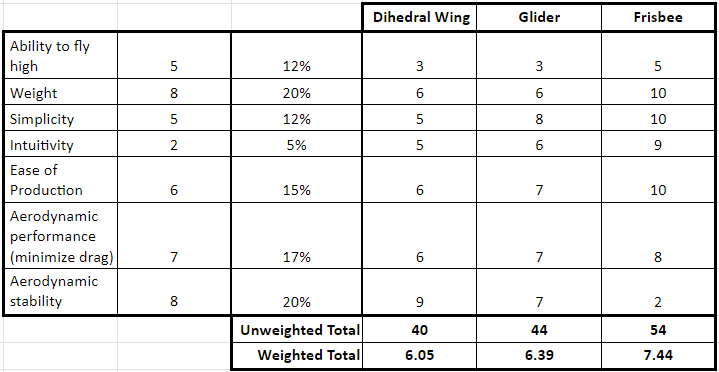
The decision matrix generated to help select the design of the aircraft. The frisbee design is the clear winner.
Once we determined the general category to be a frisbee/disc launcher design (as opposed to a linear glider aircraft launcher), we discussed several possible frisbee launcher types, including a rubber band-powered launcher, a linear spring-driven rail system, and a torsional-spring based rotating arm design. Eventually, we settled on the rotating arm design, influenced in part by Mark Rober's Rock-Skipping Robot. This design was selected due to its ability to reliably and repeatably deliver the rotational energy required for stable disc flight.
We came up with a design which we defined in four main subassemblies: the table mounting rig, the angle adjustment mechanism, the mechanical power (torque) storage & delivery unit, and the swinging arm (which holds and releases the frisbee). In total, our team modeled approximately 25 individual components for the various mechanisms and subassemblies. We made engineering drawings for each one; below are some highlights.
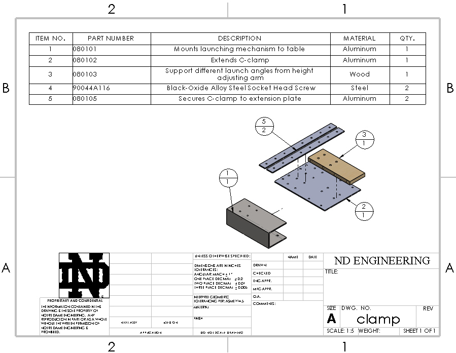
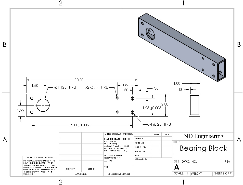
Drawing for the table mount subassembly shown on the left, and the bearing block – to support the torsional spring and main launch mechanism – on the right.
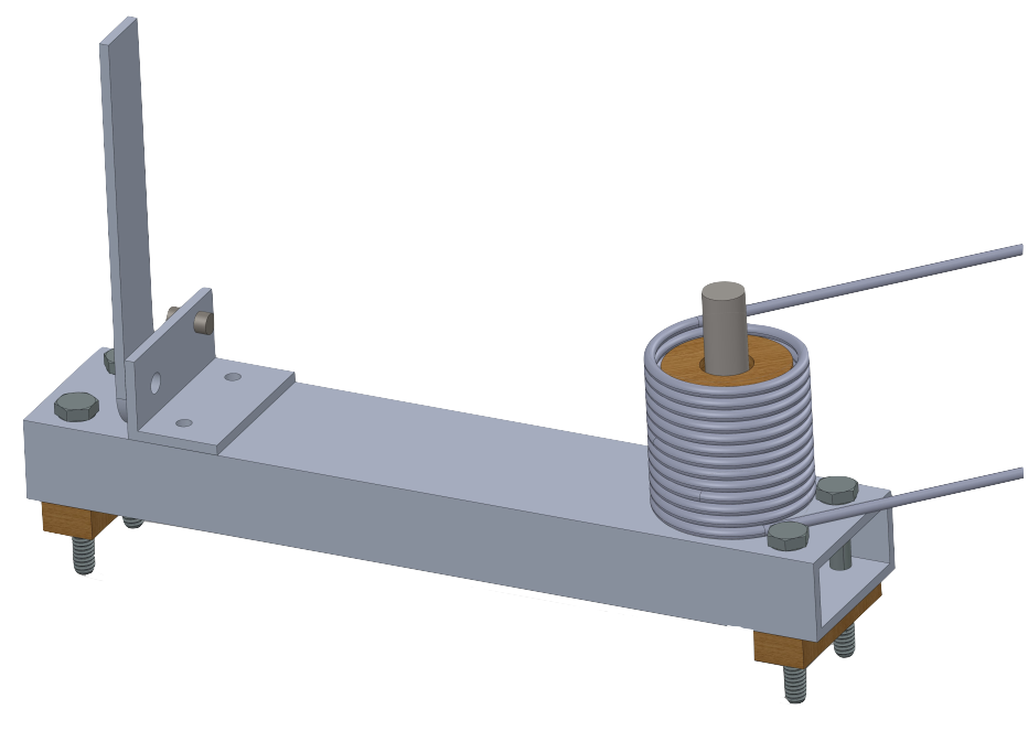
Isolated view of the bearing block subassembly containing the trigger mechanism and the torsional spring for powering the arm.
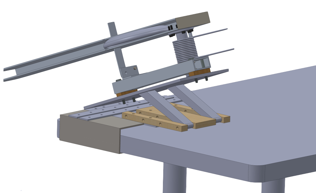
A view of the complete launcher assembly mounted to the table. The mechanism is shown in its 'loaded' configuration, with the trigger arm slotted into a groove in the launch arm.
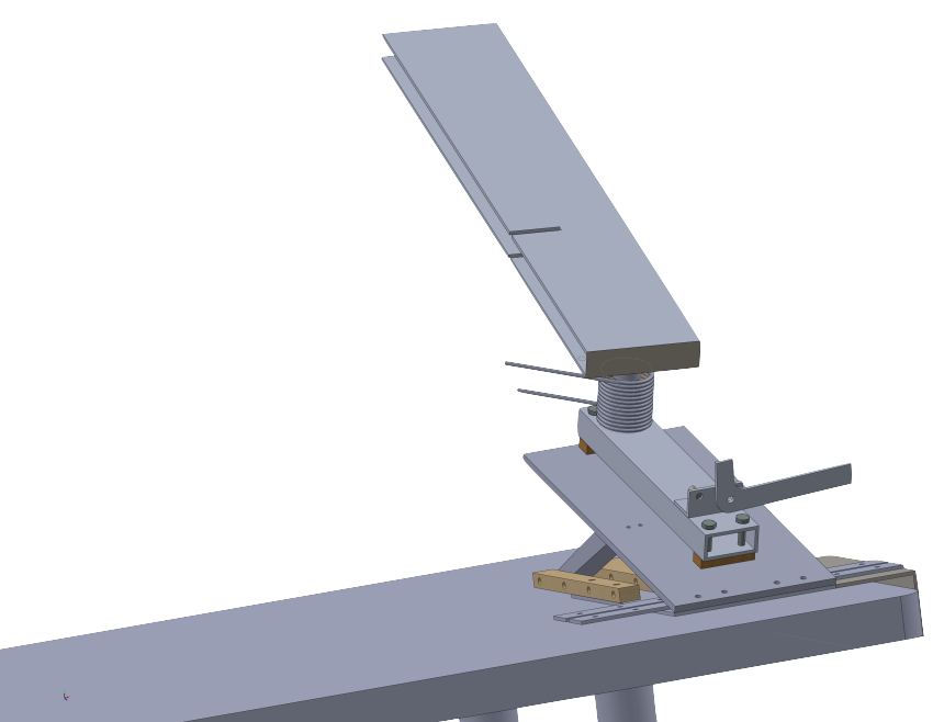
A view of the launcher shown in its 'launched' configuration, with the trigger arm out of the launch arm's way.
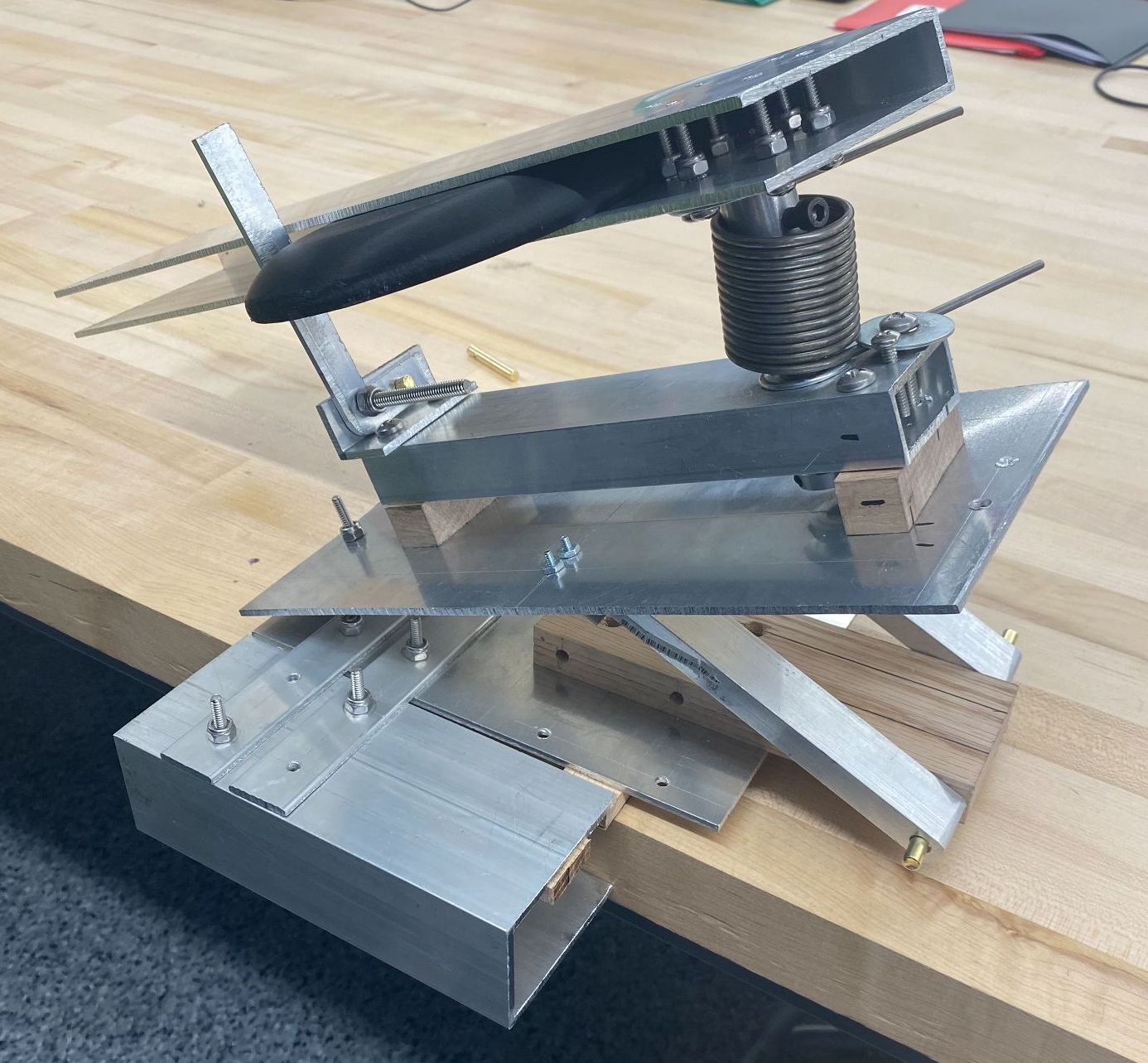
The physical prototype, shown in its low-angle launch configuration, where the angle of attack produces the greatest horizontal flight distance.
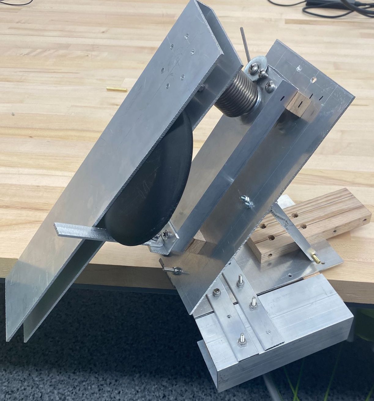
The physical prototype, shown in its high-angle launch configuration.
The final prototype matched our original design spec incredibly well. The only major change we made during construction was to the length of the launch arm, which was gradually shortened through empirical trials to optimize for launch distance and release position. Our prototype was able to consistently launch the frisbee ~20 feet, and the disc was one of only two aircraft in the class to achieve sustained flight.