Senior Design Capstone Project
Summary
As part of a small team, I designed and built a robot capable of completing an obstacle course designed by our professor. I was personally responsible for the mechanical design and computer vision for the robot’s sorting subsystem, which autonomously performed color-based sorting of bouncy balls. As the design lead for the team, I also led the finite element analysis (FEA) for critical components and CAD modeling of the entire assembly.
Skills
CAD (SolidWorks); Finite Element Analysis (Fusion 360); Programming (Python); CAM (SolidWorks); Engineering drawings; Physical prototyping; Workshop skills
Team Size
5 (myself and four peers)
Category
Coursework: Senior Design (AME 40463)
Detailed Breakdown
As part of Senior Design, our class was challenged to build a robot that was capable of navigating an Olympics-themed obstacle course created by my professor. Specifically, the robot had to carry a 25 lb weight, pick up bouncy balls, autonomously sort the bouncy balls by color, launch a bouncy ball of specified color, and complete a 100 ft dash.
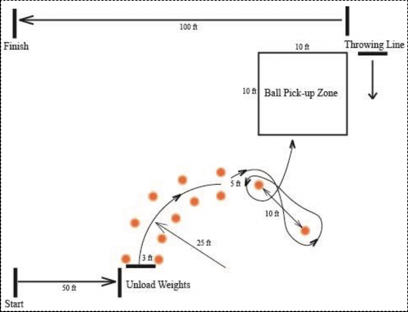
An image of the obstacle course.
To form a general plan for the robot, my group started by brainstorming several possible designs before settling on a concept. Some initial ideas and sketches are shown below.
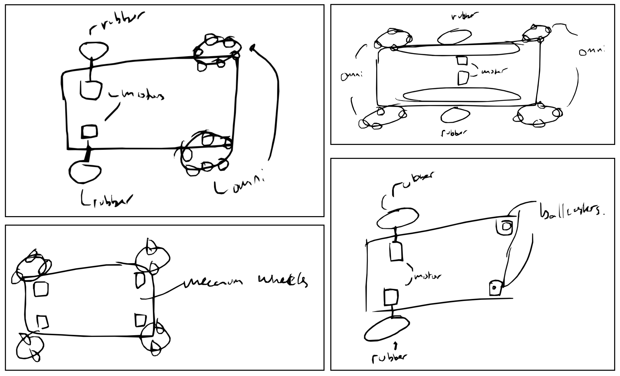
Sketches of several proposed drivetrain layouts.
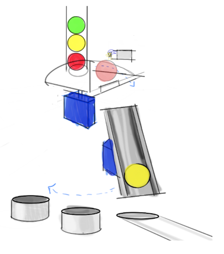
An early visualization of the proposed sorting subsystem layout.
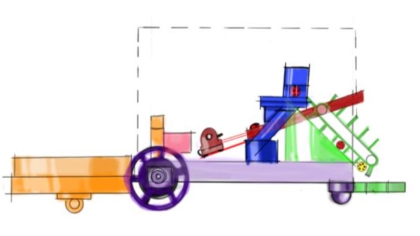
An approximate arrangement of all subsystems drawn by one of my teammates. This was done to get an idea of how the subsystems would need to be laid out to interact cohesively.
To establish individual areas of responsibility, our team divided the problem statement into five distinct subsystems: the drivetrain, ball intake system, ball sorting system, ball launching system, and detachable weight-carrying system. In addition to being the team’s mechanical design lead, I opted to take ownership of the sorting subsystem. Concretely, I was in charge of the FEA of select components and leading the development of the CAD model of the system.
One of the most significant milestones was the creation of a full CAD model of our design. We completed this step before ordering any physical material to ensure that all subassemblies had adequate space to fully function, while respecting the (self-imposed) customer requirement of compactness & transportability.
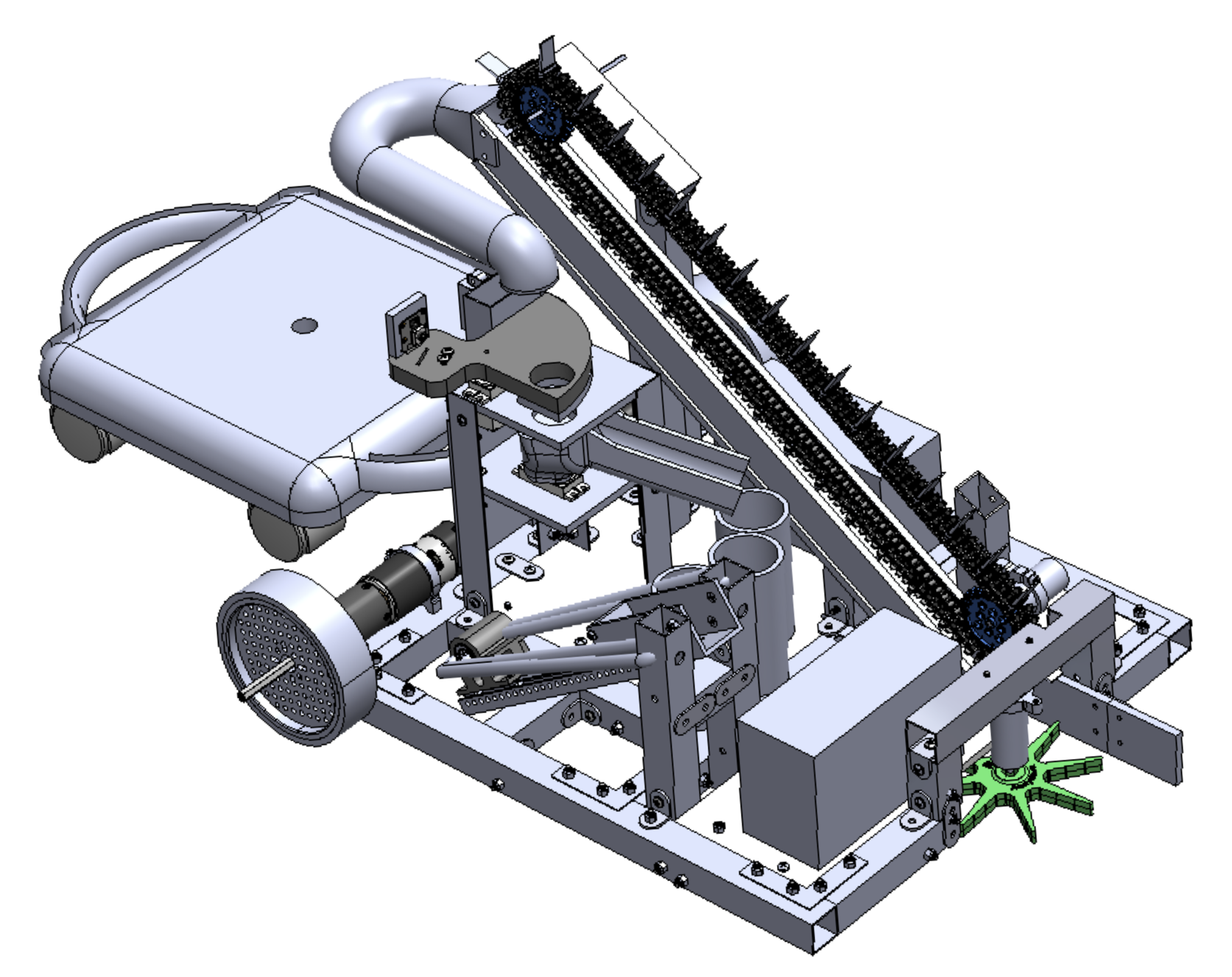
The final, complete CAD model of the whole robot.
One of the most challenging aspects of this process was the exercise of arranging and precisely aligning the subassemblies with high interdependence, namely the intake-sorting-launching sequence. The sorting subsystem required very precise pickup and dropoff points from the intake ramp and into the launcher. I navigated this complexity by adding one geometric constraint at a time, starting with the most fundamental dimensions required for each subsystem’s basic functionality. I chose to use a layered tower design (similar to a candy sorter) to house the sorting mechanism to give myself some flexibility in this regard, where the ‘legs’ of the tower could be lengthened or shortened as needed to fix misalignment with the intake or launcher systems.
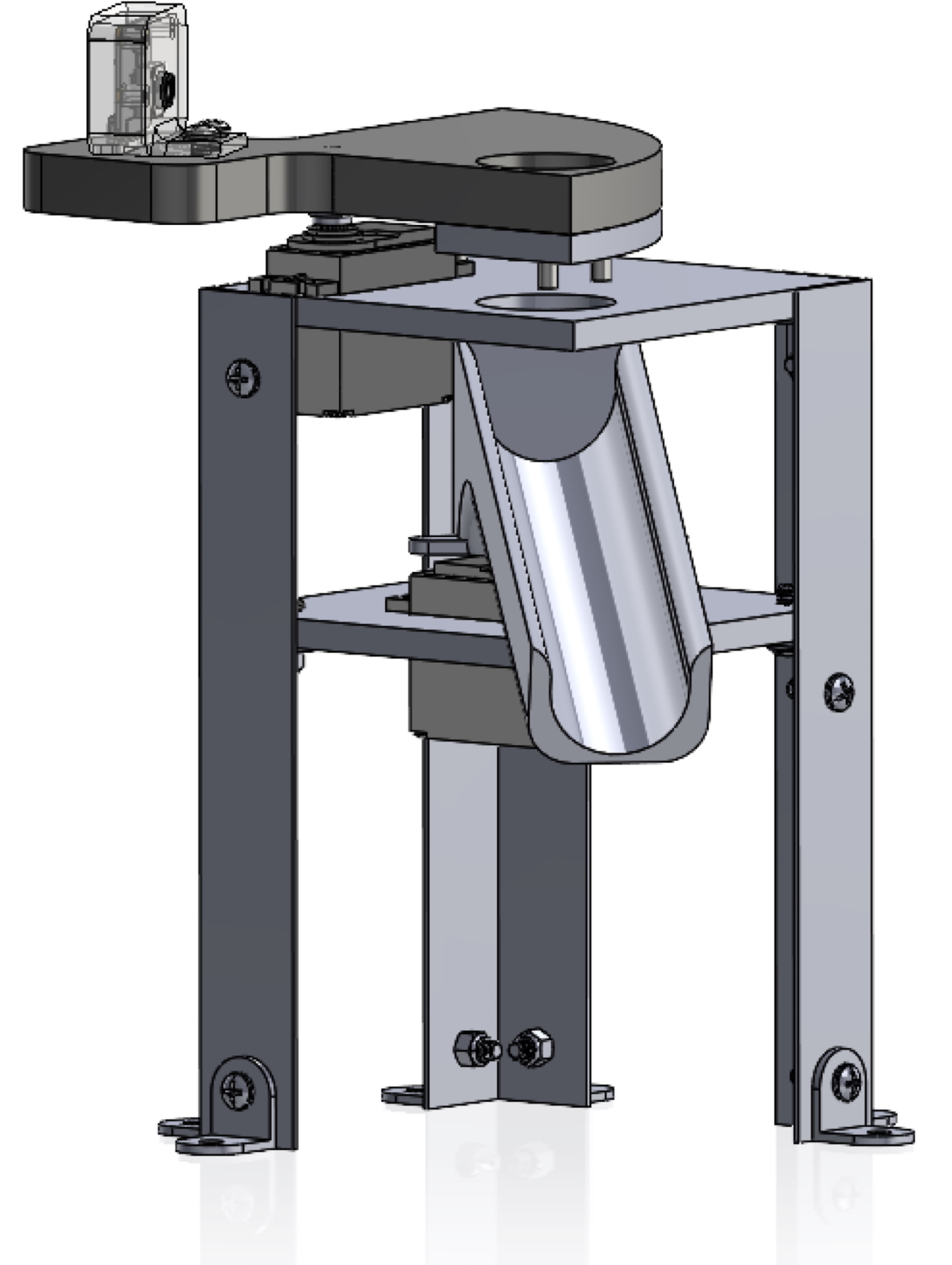
An isolated view of the sorting subsystem. The layered tower design is visible.
Our group decided to use a camera and computer vision for the color recognition. This is because the particular balls that our professor selected for the challenge had patches and stripes, which added a layer of complexity and demanded more sophistication than the simple single-point intensity-to-frequency detection offered by common color sensors.
Using a camera sensor with OpenCV allowed us to analyze multiple specific points within the image, rather than just the center of the frame. I took advantage of this by writing our own pixel sampling algorithm.
At a high level, my algorithm draws a bounding circle over the region of the frame where the ball is expected based on the fixed alignment of the camera relative to the ball. The algorithm then randomly samples 100 pixels within this circle, checking the color of each one. I implemented this additional step to maximize the likelihood of capturing the ball’s dominant color, using the uniform random distribution of pixels to diminish the effects of interference from stripes, patches, or shadows. Using the sample of 100 pixels, the computer then labels the ball a color (red, yellow, or blue) if it gets a strong match with (i.e., at least 90 instances of) one of the three possible colors. If this 90% match condition is not satisfied, the ball is instead classified as “unknown color” and ejected from the system using a servo-actuated arm. We chose this high threshold to reduce misclassifications, as we found that a simple majority condition (e.g., 65%) sometimes led to errors under challenging lighting conditions. For example, under heavily orange-tinted lighting, a yellow ball could be misclassified as red (e.g. 65 red, 26 yellow, 9 blue, 0 unknown).
To further enhance the reliability of our algorithm under suboptimal lighting conditions, I chose to implement the color detection in HSV colorspace rather than RGB. By isolating the Hue channel for color identification and using Value for brightness detection, we were able to avoid the complex RGB channel interactions that typically occur with changing ambient light. The code is available on GitHub.
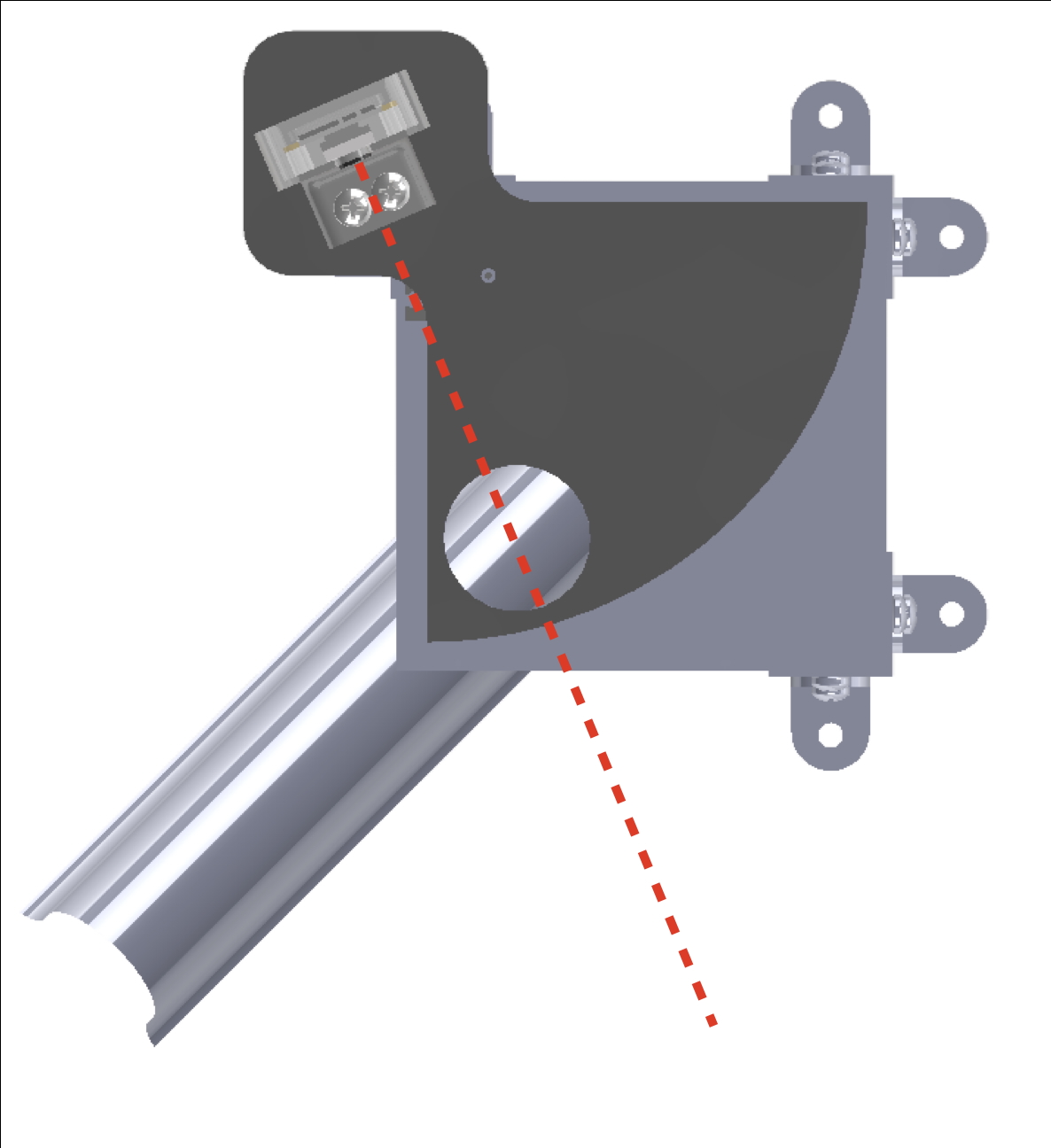
An overhead view of the sorting subsystem. The camera’s direct alignment with the ball is shown by the red dotted line.
Another engineering highlight from this project was the design of our ball launcher subsystem, for which I designed the slammer block. The system functions by rapidly accelerating this block until its impact with a ball stored in the launch channel, at which point the bulk of the block’s kinetic energy is transferred to the ball via impact (some energy is lost due to friction, deformation, and sound). To maximize the amount of energy transferred, we opted to use a tungsten carbide pin for the point of contact due to the material’s extremely high coefficient of restitution. We used a linear actuator to release a pre-loaded elastic band holding the rail-mounted block in place.
Based on our model of the launcher’s dynamics, one of my teammates determined that the ideal mass of the slamming block which would lead to the farthest launch distance was ~35 grams. This constraint made the design of the block – which we intended to machine out of aluminum – quite challenging. Our initial attempt weighed ~138 grams. After several iterations and redesigns, I had developed a version that was ~86 grams, but was struggling to shed any additional weight from the design.
With a functionality demonstration deadline fast approaching, we were running out of options for this critical component. We reluctantly decided that the safest option was to manufacture the part and make-do with its suboptimal performance. I worked with our fabrication instructor to make a CAM program for the 5-axis CNC mill.
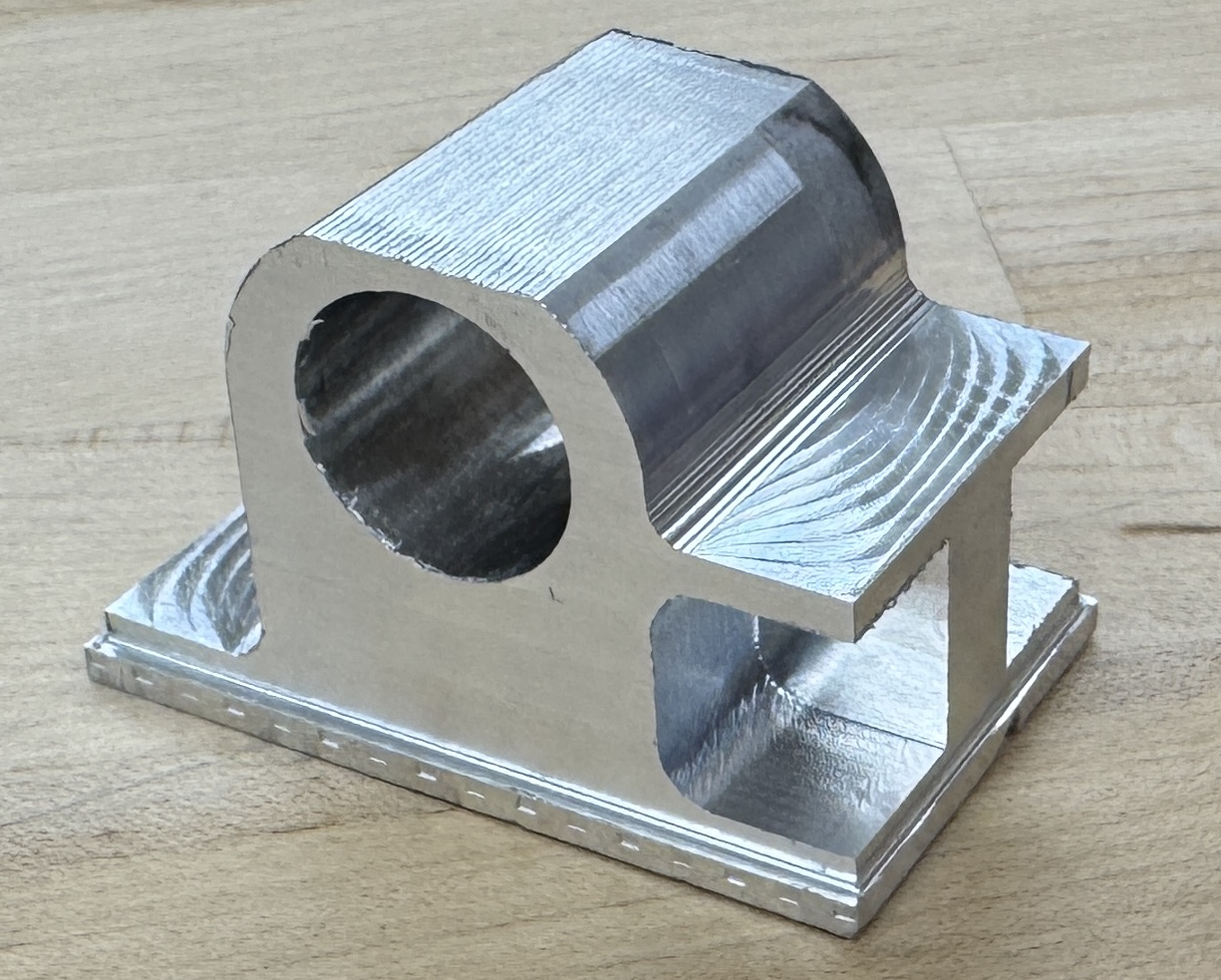
The milled aluminum slamming block.
While our initial assumptions pointed toward metal as the assumed material, it was at this point that we decided to reconsider our choice to explore alternative materials. I set up an FEA model to evaluate the feasibility of a 3D printed version, using a slightly-larger-than-expected collision force. The analysis yielded a promising factor of safety of 1.53, suggesting that a 3D printed alternative of the same part, weighing just 36 grams, could meet our performance requirements. After validating the FEA results through physical testing, we incorporated the plastic slamming block. Though the adjustment was a success, the inconvenience of this late-stage design change gave me a much-needed reminder of the importance of thorough material selection early on.
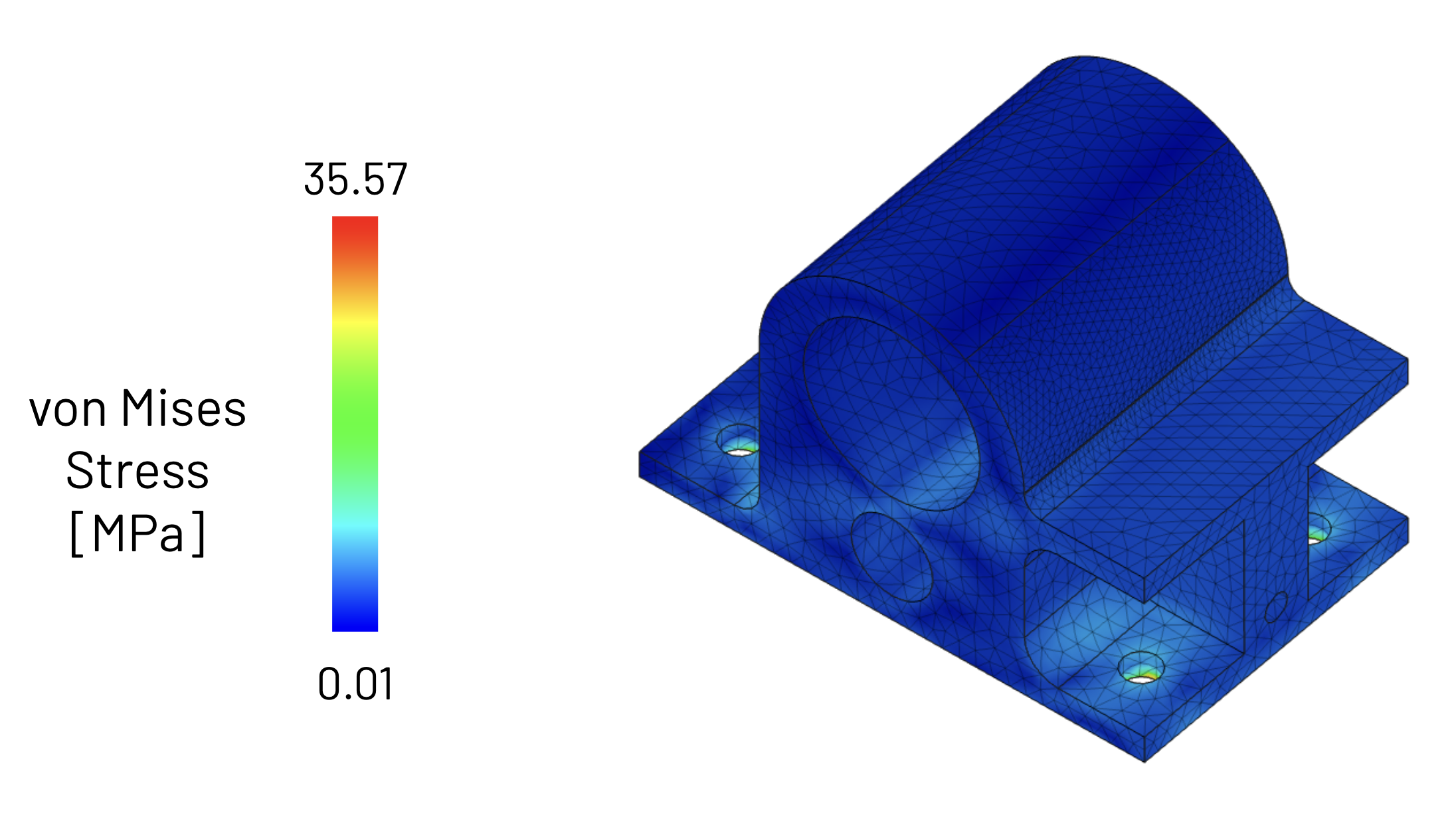
The results of the FEA simulation of the plastic part, where the block’s bottom four holes are constrained and the front profile is subjected to 400N of force from the impact.
We produced engineering drawings for each manufactured part in the system. This work was split evenly between team members.
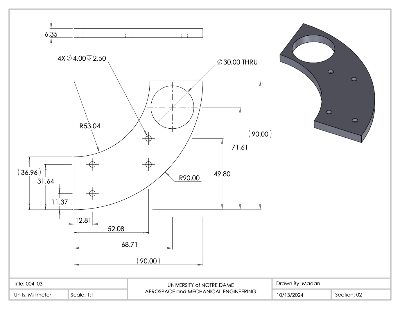
A representative sample of a part drawing. This particular part belongs to the sorting subsystem.
Our final robot, shown below, performed well. We completed the entire course during the final demonstration.
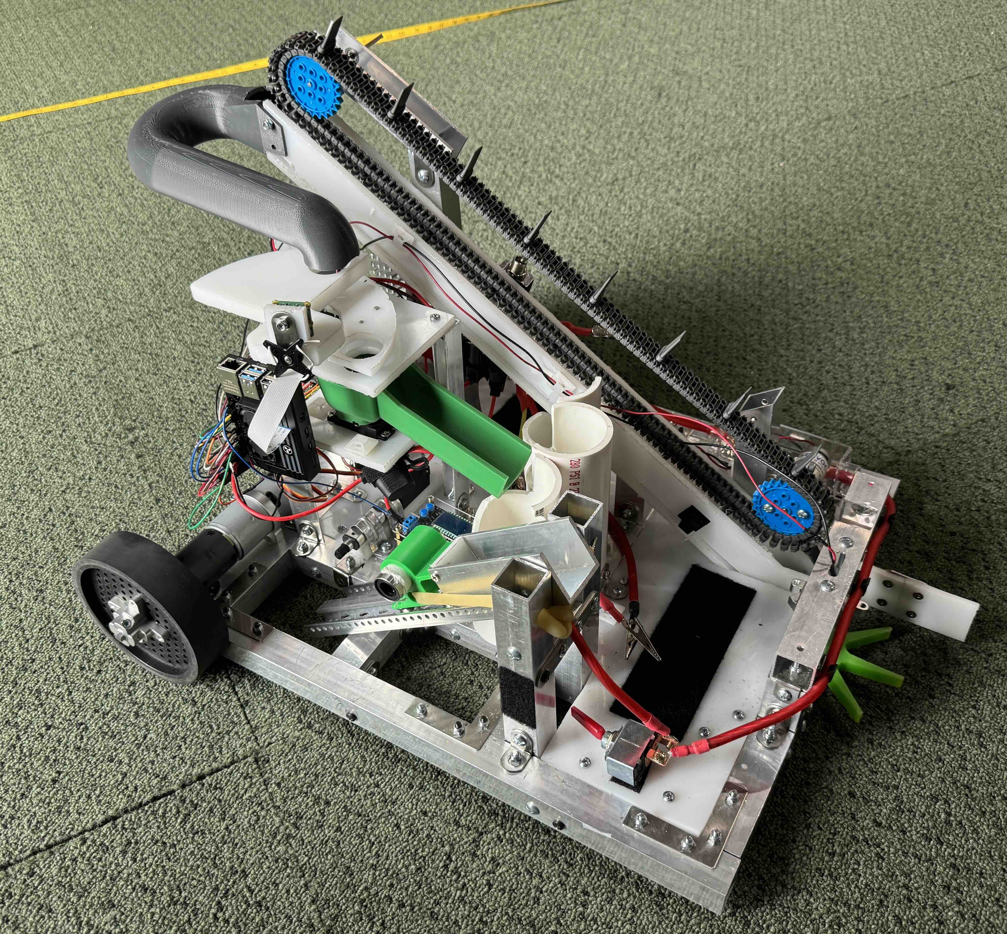
The final, complete build. The whole system weighs about 25 pounds.