Stair Climbing Robot
Summary
As part of a small team, I designed a robot which climbs stairs and delivers a small payload held in a wirelessly operable box enclosure.
Skills
CAD (SolidWorks); Motion analysis (SolidWorks); Mechanism design; Engineering drawings; Physical prototyping; Workshop skills
Team Size
4 (myself and three peers)
Category
Coursework: Design Tools II (AME 21268)
Detailed Breakdown
For the final project in this course, our class was challenged to build a stair-climbing robot which would be capable of carrying a payload of two 7.5oz (mini) soda cans with minimal disturbance or shaking of the cargo. One of the stipulations was that the soda container needed to be remotely openable and closable via a servo-actuated mechanism. I was personally responsible for the design and manufacturing of this soda box. To establish a general plan for the form of the robot, my group started by brainstorming several possible designs; two early ideas are shown below.
A sketch of a tri-spoke wheel design, with a dragging 'tail'. This design ended up being very popular among other teams.
An initial drawing of the semi-circle wheel design.
Our team evaluated the strengths of each design based on previous implementations (eg. Seoul National University’s rapid stair climbing build and a senior design project from Trine University), and ultimately decided that the four-wheeled semicircle approach offered the most linear motion.
We then constructed a simplified model of the robot (with approximately semi-circular wheels) and a staircase environment, and conducted motion analysis of three motors varying in speed: 20 RPM, 30 RPM, and 45 RPM. The 30 RPM motor (planetary gearbox with 188:1 gear ratio) was the only one of the three tested motors which provided the torque necessary to overcome the height of each stair, so we opted to use it to drive our belt & pulley power transmission system. Of course, the increased torque came at the expense of RPM — a tradeoff we deemed necessary for our given application.
Motion analysis of the 30 RPM motor configuration. Note that the wheel geometry used here was still in its early design phase.
In refining the design of the wheel, we measured the dimensions of a representative staircase to determine the arc length of each semicircle of the wheel. We found that it needed to be approximately 311 mm to allow the rolling wheels to maintain full contact with each step. This led us to the conclusion that we could create a more stable path of travel by minimizing movement in the y-axis plane by slightly increasing the wheel size. As such, we increased the wheel arc-length to 327 mm. We iterated on this geometry several times, and eventually settled on a shape defined by a parametric curve of changing radius. My team deemed this necessary to counterbalance the fact that the robot body’s height relative to the stairs naturally oscillated over traversal cycles. The final drawing of the wheel is shown below.
The final design of the wheel. Manufactured out of high-density polyethylene (HDPE) via water-jet cutting.
We designed the drivetrain to power both axles directly via a belt & pulley system in order to ensure that the wheels would always be in phase when operating — a key assumption upon which our motion analysis (and therefore wheel design) was based. The subassembly is shown below.
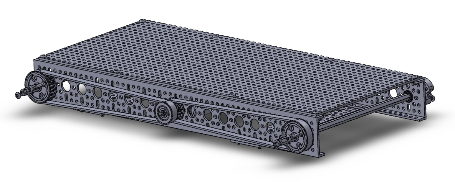
An isometric view of the frame with the main power transmission subassembly mounted.
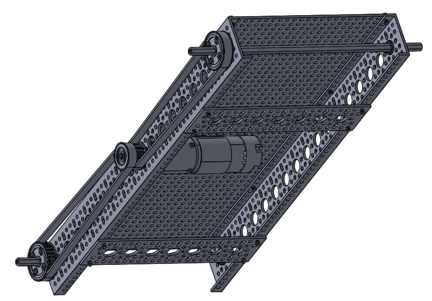
A bottom view of the same subassembly, where the motor is visible.
I designed the soda box to house the cans inside a shock-absorbing foam block to cushion the cans from the minor remaining shaking and bumpiness of the robot body. The container was designed to operate with a rear-mounted servo, which pulls down the lever arm on the back of the soda box lid to move it to the open position.
A model of the soda box holder, shown collapsing from an exploded view. The lid's final position in this animation is half-open to show the contents inside.
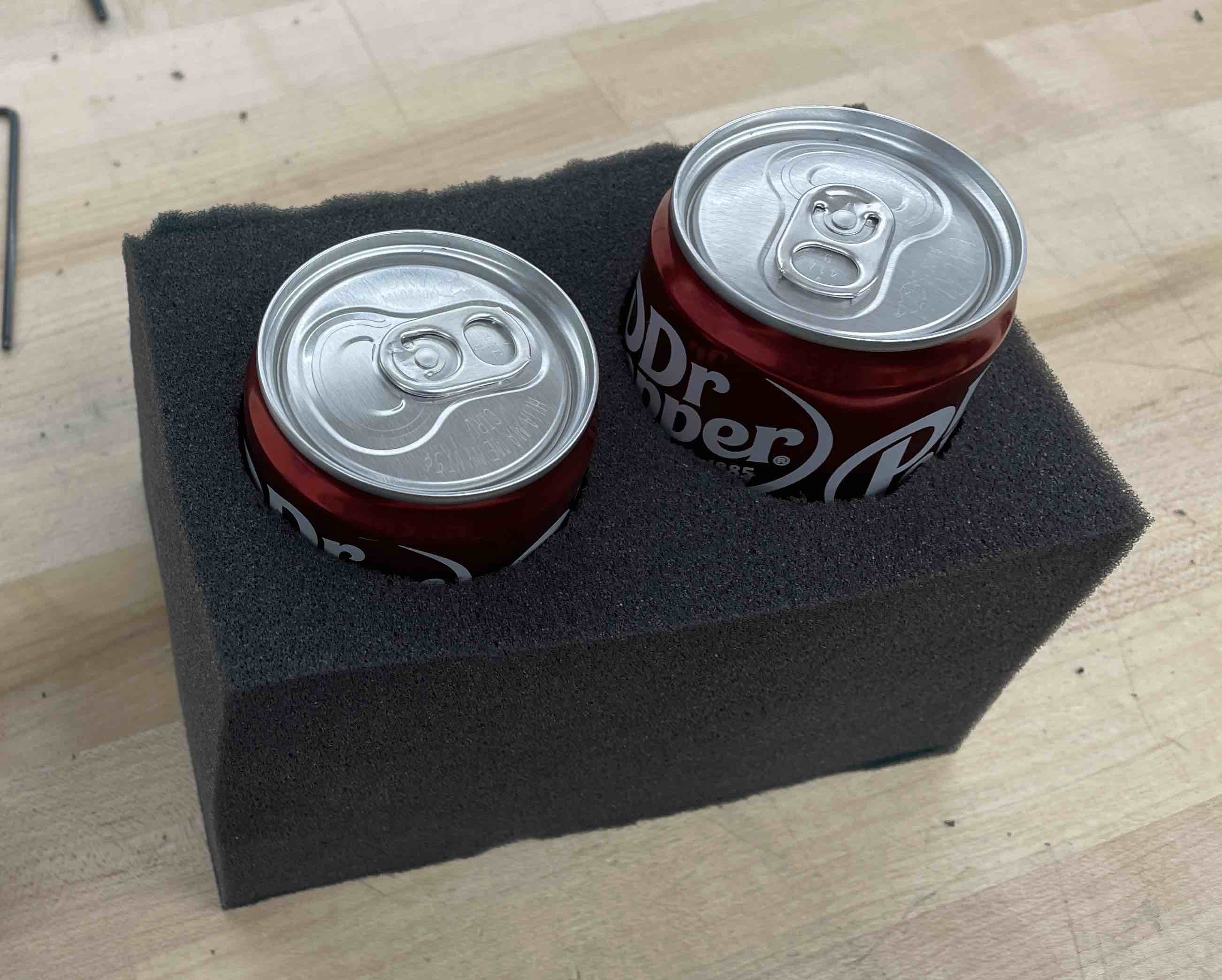
Soda cans sitting in shock-absorbing polyurethane padding.
Close-up view of the lid mechanism. The rear-mounted servo controls the lid's position via a thin steel 'music wire'.
Once my team had finalized the design of all of the main subassemblies and components, we assembled the robot in the configuration shown below. Note that the battery and wireless receivers are not included in the model.
Drawing showing an exploded view of the main assembly.
We did not account for the weight of the cargo or battery in the simplified model of the robot that we used in our initial motion analysis. This led to some imbalance issues and “flopping” behavior of the robot during testing of the initial physical prototype. The discrepancy between simulation and actual behavior showed us firsthand the perils of oversimplifying physical systems during simulation — one of the most valuable lessons I learned through this project.
Luckily, our motor was powerful enough to supply the torque needed to overcome this added, previously unaccounted-for weight. We did, however, face some challenges with the slipperiness of the HDPE wheels, which, under the added weight, had trouble gripping the ground, causing the whole robot to slide down the stairs. We addressed the weight distribution problem by repositioning the bulky battery on the body until we were satisfied with the stability of the robot. Our team solved the sliding problem by adding a layer of anti-slip rubber tape to the outer rims of the wheels. These two solutions were enough to resolve the stability and grip issues.
Our final robot, shown below, performed well. On demonstration day, the soda cans were successfully transported up the staircase and were accessed & opened without violent fizzing or exploding. I made a short video of the project (just for fun), which you can check out here.
The final CAD model.
The final physical prototype.
The robot successfully climbing stairs on demo day.